48+ Symbols For Circuit Diagrams
Each component has its own symbol. Web What Are the Basic Electrical Symbols.
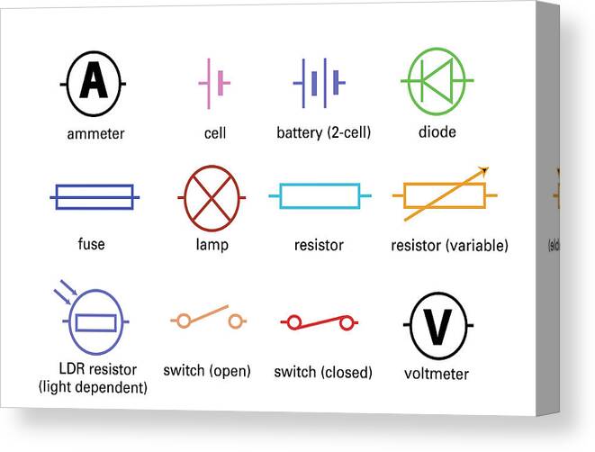
Standard Electrical Circuit Symbols Canvas Print Canvas Art By Sheila Terry Fine Art America
Resistors on a schematic are usually represented by a few zig-zag lines with two terminals extending outward.

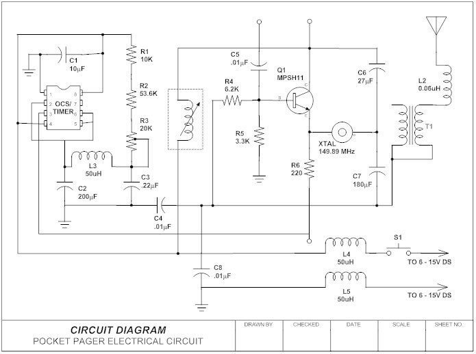
. Circuit Diagrams Circuit symbols are used in circuit diagrams which show how a circuit is connected together. Web Common circuit diagram symbols. Circuit diagrams use nationally or internationally recognised symbols to represent the individual components used in the construction of that circuit.
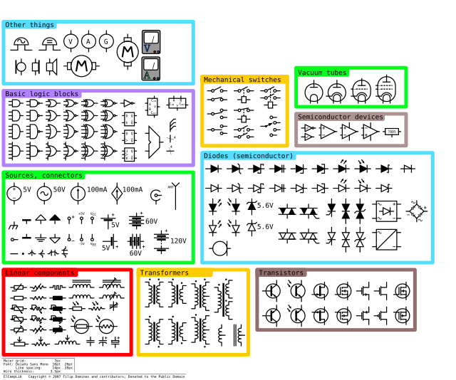
All circuit symbols are in standard format and can be used for drawing schematic circuit diagram and layout. The most common circuit symbols are those used for the cell battery switch resistor ammeter voltmeter lamp fuse diode and LED. Each electronic component has a symbol.
Web Learn to define what an electrical circuit is. Wiring diagram electrical diagram elementary diagram electronic schematic is a graphical representation of an. Like transistors ground wires bulbs batteries resistors etc.
Web The circuit symbols represent the various Circuit and electronic components in a circuit diagram in the Circuit and electronics world. The most fundamental of circuit components and symbols. In schematics many components are also represented by a letter code shown in.
Here are some of the standardized basic schematic symbols for various components. Learn the current formula and the current unit. Httpsbitly3laQew6 Explore Electrical Wiring Diagrams and free use and edit 5000 diagram examples her.
Two Types of Connections. Logic gate circuit diagram symbols. Elements The term elements means components and sources Symbols Elements are represented in schematics by symbols.
In order to learn how to read a circuit diagram it is necessary to learn what the schematic symbol of a. To build a circuit you need a different diagram showing the layout of the parts on stripboard or printed circuit board. Web 48 - Incomplete-Sequence Relay 49 - Machine or Transformer Thermal Relay 50 - Instantaneous Overcurrent 51 - AC Time Overcurrent Relay 52 - AC Circuit Breaker 53 - Exciter or DC Generator Relay 54 - High-Speed DC Circuit Breaker 55 - Power Factor Relay 56 - Field Application Relay 59 - Overvoltage Relay 60 - Voltage or Current.
Web Discover the fundamentals of circuit diagrams including how to read them and interpret various circuit components. EO 11 IDENTIFY the symbols used on engineering electronic block diagrams prints and schematics for the following components. Web They are the symbols given to electrical components in order to differentiate them from each other in a circuit diagram.
Electrical circuit diagram symbols. The actual layout of the components is usually quite different from the circuit diagram. 15 Given a simple electrical schematic and initial conditions DETERMINE the condition of the specified component ie energizedde-energized.
Electrical Diagrams and Schematics vi ENABLING OBJECTIVES Cont 14 STATE the condition in which all electrical devices are shown unless otherwise noted on the diagram or schematic. Common schematic diagram symbols US symbols The circuit diagram for a four-bit TTL counter a type of state machine. These include symbols such as relays transducers transformers power supplies logic gates and other components.
After seeing a few circuit diagrams youll quickly learn how to distinguish the different symbols. Web Schematic Symbols Part 1 Are you ready for a barrage of circuit components. Relay circuit diagram symbols.
These are the most basic electrical diagram symbols which can represent simple circuits. A circuit diagram or. Comparison of pictorial and schematic styles of circuit diagrams.
Web Circuit Symbols and Circuit Diagrams. Web To read and understand an electronic diagram or electronic schematic the basic symbols and conventions must be understood. Without these symbols we will never be understood and analyze what the circuit diagram is trying to explain to us.
Web In addition to the common symbols mentioned above there are many other circuit diagram symbols that are used to represent more complex components operations and connections. Voltmeters charge symbols waves and. Web A schematic represents circuit elements with symbols and connections as lines.
What are the most common circuit symbols. The components required to build the circuit. A circuit diagram shows us.
They use lines between those components to represent the connections between the components. Web With dozens of industry-standard shapes to choose from you can create schematic or pictorial circuit diagrams wiring diagrams and other electrical diagrams. Web The graphic symbols used for electrical components in circuit diagrams are covered by national and international standards in particular.
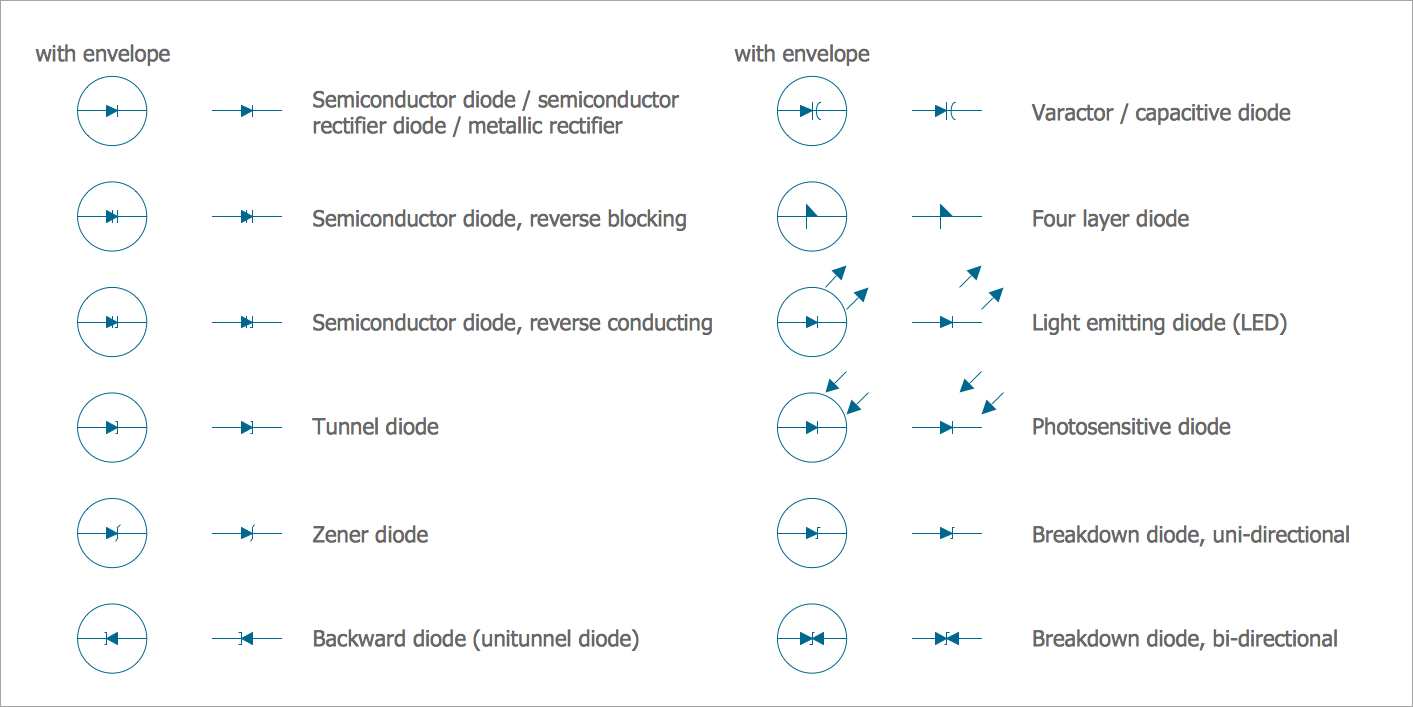
Web Circuit or schematic diagrams consist of symbols representing physical components and lines representing wires or electrical conductors. Discover the circuit diagram and the circuit symbols. Web 5 Complete circuit symbols of electronic components.
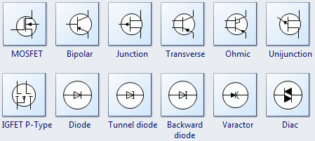
Choose from electrical power sources transistors relays logic gates and other standard symbols. Transistor circuit diagram symbols. Web Circuit Diagram Symbols Learn More How to Make a Circuit Diagram Learn More Wiring Diagram Learn More Block Diagram Learn More Circuit Diagram Examples Learn More With SmartDraw You Can Create More than 70 Types of Diagrams Charts and Visuals Learn More Circuit Diagram Examples.
IEC 60617 also known as BS 3939. Explore practical examples and understand the symbols used to denote batteries resistors voltmeters and more. Thus far this unit of The Physics Classroom tutorial has focused on the key ingredients of an electric circuit and upon the concepts of electric potential difference current and resistance.
Web A circuit diagram or a schematic diagram is a technical drawing of how to connect electronic components to get a certain function. Web Free download EdrawMax and create Electrical Diagrams or Electric Circuits easily. Power source circuit diagram symbols.
There is also IEC 61131-3 for ladder-logic symbols.
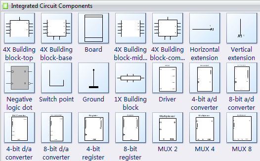
Circuit Component Symbols For Integrated Circuit Drawings Edraw

Circuit Diagram Symbols Lucidchart
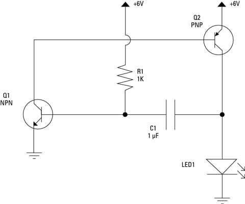
Electronics Schematics Commonly Used Symbols And Labels Dummies
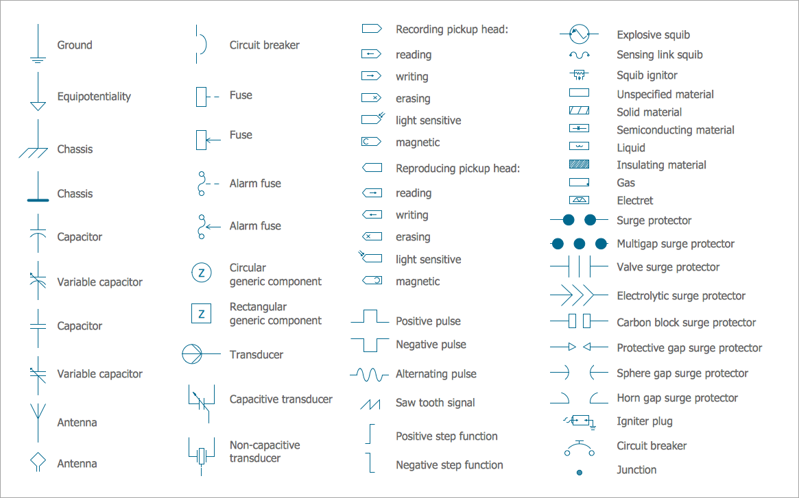
Electrical Symbols Electrical Diagram Symbols
Circuit Diagram Everything You Need To Know Edrawmax Online
Electrical Schematic Symbols Circuitstune

10 097 Circuit Diagram Symbols Images Stock Photos Vectors Shutterstock
Circuit Diagram Symbols A Complete List Edrawmax
Electrical Symbols Electrical Diagram Symbols

Electrical Schematic Symbols Circuitstune

Electronic Component Lists And Schematic Symbols Free Online Pcb Cad Library
![]()
10 097 Circuit Diagram Symbols Images Stock Photos Vectors Shutterstock

The Most Common Schematic Symbols Used In Electronics

10 097 Circuit Diagram Symbols Images Stock Photos Vectors Shutterstock

100 Electrical Electronic Circuit Symbols

Electrical Symbol Chart Electrical Symbols Electrical Schematic Symbols Electronic Schematics
File Electrical Symbols Library Svg Wikimedia Commons